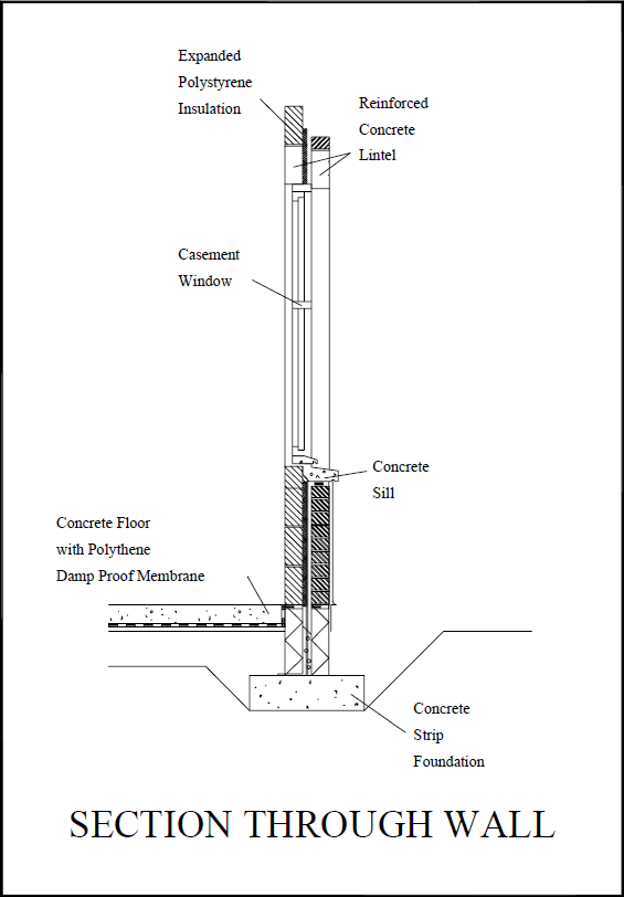
Component drawing
A component is a constituent part of a building (or other built asset) which is manufactured as an independent unit, subsystem or subassembly, that can be joined or blended with other elements to form a more complex item. Generally, components are ‘self-contained’ and sourced from a single supplier, typically the complete unit provided by that supplier rather than its constituent parts.
A combination of components may be described as an ‘assembly’.
Where a component is a bespoke item, it may be necessary to prepare a component drawing. Where a component is an off-the-shelf-product or a commonly-used element, a component drawing may already exist that can be re-used.
Component drawings might describe units such as; beams, windows, doors, sills, coping stones, and so on.
Component drawings provide detailed information about the individual units. They may be drawn at large scales such as; 1:10, 1:5, 1:2, 1:1, and so on. They may include information such as component dimensions, construction, tolerances, and so on. They may include references to the relevant parts of the specification providing information about materials and the minimum acceptable quality.
It is important that component drawings do not duplicate information included in separate specifications as this can become contradictory and may cause confusion.
Component drawing numbers may be prefixed by the letter C.
Component range drawings describe a range of components of a similar type. Where a range of components comprise a number of standard constructions, sub-component drawings may be prepared.
Assembly drawings represent items that consist of more than one component, showing how the components fit together.
[edit] Find out more
[edit] Related articles on Designing Buildings Wiki
- As-built drawings and record drawings
- Assembly drawing.
- CAD layer.
- Concept drawing.
- Design drawings.
- Detail drawing.
- Electrical drawing.
- Elevations.
- Engineering drawing.
- Exploded view.
- General arrangement drawing.
- Geometric form.
- Installation drawing.
- Orthogonal plan.
- Plumbing drawing.
- Projections.
- Scale drawing.
- Shop drawing.
- Section drawing.
- Technical drawing.
- Types of drawing.
- Working drawing.
Featured articles and news
Infrastructure that connect the physical and digital domains.
Harnessing robotics and AI in challenging environments
The key to nuclear decommissioning and fusion engineering.
BSRIA announces Lisa Ashworth as new CEO
Tasked with furthering BSRIA’s impressive growth ambitions.
Public buildings get half a million energy efficiency boost
£557 million to switch to cleaner heating and save on energy.
CIOB launches pre-election manifesto
Outlining potential future policies for the next government.
Grenfell Tower Inquiry announcement
Phase 2 hearings come to a close and the final report due in September.
Progress from Parts L, F and O: A whitepaper, one year on.
A replicated study to understand the opinion of practitioners.
ECA announces new president 2024
Electrical engineer and business leader Stuart Smith.
A distinct type of countryside that should be celebrated.
Should Part O be extended to existing buildings?
EAC brands heatwave adaptation a missed opportunity.
Definition of Statutory in workplace and facilities management
Established by IWFM, BESA, CIBSE and BSRIA.
Tackling the transition from traditional heating systems
59% lack the necessary information and confidence to switch.
The general election and the construction industry
As PM, Rishi Sunak announces July 4 date for an election.
Eco apprenticeships continue help grow green workforce
A year after being recognised at the King's coronation.
Permitted development rights for agricultural buildings
The changes coming into effect as of May 21, 2024.


